
Secure-Timeout-System-NXPS32K3X8EVB
![]()
Table of Contents
• [Project Overview](#project-overview)• [Features](#features)
• [Getting Started](#getting-started)
• [Prerequisites](#prerequisites)
• [Installation](#installation)
• [Running the Emulator and the Application](#running-the-emulator-and-the-application)
• [Guide for Recreating the Project](#guide-for-recreating-the-project)
• [Project Structure](#project-structure)
• [Board Specifications](#board-specifications)
• [Memory](#memory)
• [Peripherals](#peripherals)
• [FreeRTOS Application](#freertos-application)
• [Available Configuration Options](#available-configuration-options)
• [Memory Protection Unit (MPU) Implementation](#memory-protection-unit-mpu-implementation)
• [Team Collaboration](#team-collaboration)
• [Contributing](#contributing)
• [Authors](#authors)
• [License](#license)
• [Acknowledgments](#acknowledgments)
Project Overview
This project implements a very simple Secure Timeout System application on the NXP S32K3X8EVB board using FreeRTOS, emulated with QEMU.
This project has been assigned for the Computer Architectures and Operating Systems course at Politecnico di Torino. The work has been carried out by group 2. For more information about the authors, please refer to the Authors section.
- Original Project Repository: neo-CAOS/Secure-Timeout-System-NXPS32K3X8EVB
- Original Beamer Repository: neo-CAOS/latex-beamer
Features
- Integration with FreeRTOS: Seamlessly integrates with the FreeRTOS real-time operating system.
- UART Communication: Supports UART communication for serial data transmission.
- Hardware Timer Initialization and Handling: Initializes and handles hardware timers efficiently.
- Secure Timeout System with Multiple Tasks: Implements a secure timeout system capable of managing multiple tasks.
- QEMU Emulation Support: Provides support for QEMU emulation to facilitate testing and development.
Getting Started
Prerequisites
- A Linux-based operating system (e.g., Ubuntu)
- Git for version control
- QEMU for hardware emulation
- FreeRTOS for the real-time operating system
- ARM GCC Toolchain (
gcc-arm-none-eabi) for compiling the code - Make for building the project
- Ninja build system for building QEMU
Installation
Clone the repository:
git clone --recurse-submodules https://baltig.polito.it/caos2024/group2.git
cd group2
Running the Emulator and the Application
- To configure and build QEMU, just do:
cd App
make qemu_build
This implicitly does
make qemu_configure qemu_ninja. - To run the App:
make runThis implicitly does
make clean all qemu_start. - To run the App in debug mode:
make qemu_debugThis starts QEMU in debug mode, allowing you to connect a debugger like GDB.
There is also a command to build and run:
  cd App
  make jesus
For
make jesusandmake qemu_build, there are “verbose” versions that print the logging of the build of the board:make qemu_build_v make jesus_v
Guide for Recreating the Project
For a detailed guide on setting up, running, and recreating the project, refer to the GUIDE.md file. This guide provides comprehensive instructions and explanations of all the steps and details involved in the project.
Project structure
App/: Contains the main project files and source code.CMSIS/: CMSIS headers and startup files.MPU/: MPU files.Peripherals/: Contains peripheral driver files.IntTimer.c/.h: Timer interrupt handling.uart.c/.h: UART communication functions.
SecureTimeoutSystem/: Contains the secure timeout system implementation.globals.h: Global variables for the secure timeout system.secure_timeout_systems.c/.h: Secure timeout system functions.
FreeRTOSConfig.h: FreeRTOS configuration file.main.c: Main application entry point.Makefile: Build configuration and rules.s32_linker.ld: Linker script for the project.s32_startup.c: Startup code for the S32K3X8EVB board.
FreeRTOS/: FreeRTOS kernel and related files.qemu/: QEMU emulator files.resources/: Additional resources such as images and documentation.scripts/: Collection of scripts used in the project.README.md: Project documentation.GUIDE.md: Detailed guide for setting up, running, and recreating the project, explaining all the steps and details.LICENSE: License file.
Board Specifications
The specific board that we are implementing and should refer to is the S32K358EVB.
Memory
Flash Memory Layout
The board is equipped with multiple blocks of flash memory, each with specific starting addresses and sizes. Here is an overview of the memory blocks:
- Block 0: 2 MB at
0x00400000 - Block 1: 2 MB at
0x00600000 - Block 2: 2 MB at
0x00800000 - Block 3: 2 MB at
0x00A00000 - Block 4: 128 KB at
0x10000000 - Utest: 8 KB at
0x1B000000
The following picture provides a detailed overview of the FLASH memory layout. Refer to the last column for the implementation that was used for the project.

SRAM,DTCM,ITCM Memory Layout
The board features several blocks of SRAM and additional DTCM and ITCM block, each one starting at a specific address.
SRAM Layout:
- Block 0: 256 KB at
0x20400000 - Block 1: 256 KB at
0x20440000 - Block 2: 256 KB at
0x20480000
DTCM Memory Blocks:
- DTCM0: 128 KB at
0x20000000 - DTCM2: 128 KB at
0x21800000
ITCM Memory Blocks:
- ITCM0: 64 KB at
0x00000000 - ITCM2: 64 KB at
0x00010000
The layout is shown in the image below for reference. Refer to the last column for the implementation that was used for the project.

MPU
The MPU is configured with 16 memory regions, split across 2 blocks.
NVIC
NVIC (Nested Vectored Interrupt Controller):
- Configured with 4 priority bits and 256 IRQs:
1Initial Stack Pointer value (-16)15System Exceptions240External Interrupts

Peripherals
Peripherals and Memory Mapping
UART Base Address:
0x4006A000PIT Timer Base Addresses:
- Timer 1:
0x40037000 - Timer 2:
0x40038000 - Timer 3:
0x40039000
- Timer 1:
- LPUART Configuration: The board has 16 LPUART peripherals, and they are mapped starting from the UART base address.
- LPUART 0, 1 , and 8 are clocked by AIPS_PLAT_CLK
- The remaining LPUART are clocked by AIPS_SLOW_CLK
A detailed overview of the LPUART setup is provided in the following diagram:

Clocks
- Primary System Clock:
240MHzfrequency, 4.16ns period. - AIPS Platform Clock:
80MHz - AIPS Slow Clock:
40MHz - Reference Clock:
1MHz
Board Diagram
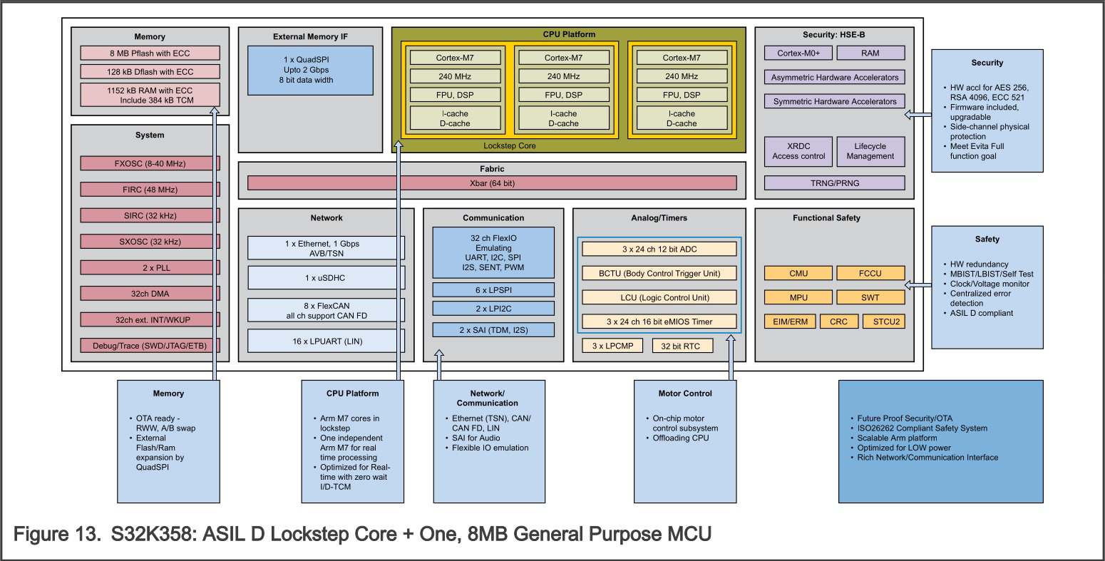 [^5] [^5]: Image taken from the manual [`S32K3xx-datasheet.pdf`](https://github.com/neo-CAOS/Secure-Timeout-System-NXPS32K3X8EVB/blob/main/resources/datasheets/S32K3xx-datasheet.pdf), page 11.
Note
These specifications were derived with reference to the NXP S32K3X8EVB board equipped with the S32K358 microcontroller. For more detailed information, please refer to the official documentation available on the NXP S32K3X8EVB product page.
FreeRTOS Application
The FreeRTOS application includes tasks for monitoring user activity, handling alerts, and simulating events. The tasks are created and managed by FreeRTOS, and the system uses hardware timers for periodic operations.
Available Configuration Options
mainTASK_PRIORITY: Priority for the main tasks. Default value:tskIDLE_PRIORITY + 2MONITOR_TASK_PRIORITY: Priority for the monitor task. Default value:tskIDLE_PRIORITY + 2ALERT_TASK_PRIORITY: Priority for the alert task. Default value:tskIDLE_PRIORITY + 3EVENT_TASK_PRIORITY: Priority for the event task. Default value:tskIDLE_PRIORITY + 4tmrTIMER_0_FREQUENCY: Frequency for Timer 0. Default value:2ULtmrTIMER_1_FREQUENCY: Frequency for Timer 1. Default value:2ULtmrTIMER_2_FREQUENCY: Frequency for Timer 2. Default value:2UL
Memory Protection Unit (MPU) Implementation
In this section, we outline the process of enabling and configuring the Memory Protection Unit (MPU) for the ARM Cortex-M7 core in our project. The full implementation details are available in the GUIDE.md file. Here, we summarize our findings and the theoretical steps required for implementation.
Research and Findings
Our research revealed that while FreeRTOS provides MPU support for ARM Cortex-M4 cores, direct support for Cortex-M7 was not explicitly documented. Key insights include:
- MPU Region Support: The Cortex-M7 processor supports up to 16 MPU regions.
- FreeRTOS MPU Port: The existing FreeRTOS port for
ARM_CM4_MPUcan be adapted for Cortex-M7. - Errata
837070: For Cortex-M7 revisionsr0p0andr0p1, Errata837070necessitates specific workarounds to ensure correct MPU functionality.
Theoretical Steps for Implementation
- Define MPU Region Count: Set
configTOTAL_MPU_REGIONSto 16 inFreeRTOSConfig.hto match the Cortex-M7’s capabilities. - Enable Errata Workaround: For Cortex-M7
r0p0orr0p1revisions, define the target to apply the necessary workaround. - Modify
port.c: Integrate the workaround as outlined in the FreeRTOS pull request #513.
Summary
By adapting the existing FreeRTOS ARM_CM4_MPU/port.c and applying necessary modifications, we aim to enable MPU support for the ARM Cortex-M7 core in our project. However, due to the complexity of the problem, the full implementation is still in progress.
For detailed code implementations and specific changes, please refer to the GUIDE.md file.
Authors
| Name | GitHub | ||
|---|---|---|---|
| Andrea Botticella | |||
| Fabrizio Emanuel | |||
| Elia Innocenti | |||
| Renato Mignone | |||
| Simone Romano |
License
This project is licensed under the Creative Commons Attribution-NonCommercial 4.0 International (CC BY-NC 4.0) license.
What This Means:
- Attribution: You are free to share (copy, redistribute) and adapt (remix, transform, build upon) the material as long as proper credit is given to the original author(s).
- Non-Commercial: You may not use the material for commercial purposes.
For more details and templates, refer to:
By using this project, you agree to the terms of the CC BY-NC 4.0 license.
Acknowledgments
- Stefano Di Carlo (stefano.dicarlo@polito.it): the professor who assigned us the project and is teaching the course CAOS.
- Team Members: Andrea Botticella, Fabrizio Emanuel, Elia Innocenti, Renato Mignone, and Simone Romano.
Please cite us if this project is copied, used for inspiration, or if any material is taken from it.
Image taken from the manual
AN13388.pdf, page 3. ↩Image taken from the manual
AN13388.pdf, page 13. ↩Image taken from the manual
S32K3XXRM.pdf, page 53. ↩Image taken from the manual
S32K3XXRM.pdf, page 4588. ↩